
The main aim here is to be able to demonstrate ClearPass OnConnect with Aruba switch 2920 in which, based on the profiled device category on ClearPass, the devices (IoTs) will be put into their respective VLANs and all this is based on SNMP.
| ClearPass | 192.168.0.95/24 | |
| DHCP server | 192.168.0.254/24 | |
| Aruba switch 2920 | 192.168.0.251/24 | |
| VLAN 100 | 10.0.10.1/24 | Non-Domain Laptops |
| VLAN 200 | 10.0.20.1/24 | Guest |
| VLAN 300 | 10.0.30.1/24 | Cameras |
| VLAN 400 | 10.0.40.1/24 | APs |
So the way it works is that the
- Device gets plugged into the switch port.
- Switch send a SNMP Trap to ClearPass along with DHCP Request info
- WebAuth is simulated internally by ClearPass when the SNMP trap is received from the switch.
- ClearPass will profile the device (DHCP, NMAP, WMI)
- ClearPass Assigs enforcement profile
- ClearPass sends Execute SNMP enforcement to the switch.
ClearPass Configuration
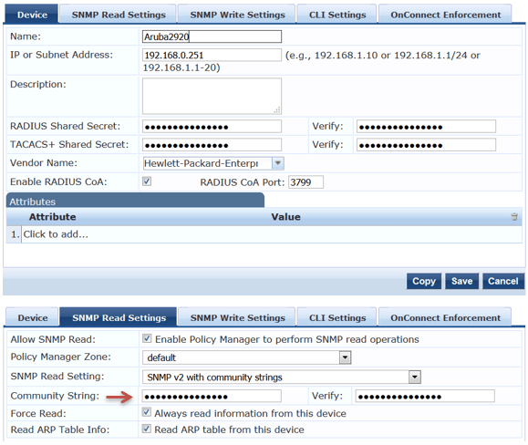
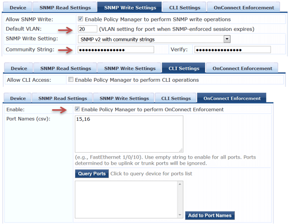
Here we will add our Aruba Switch 2920 as a NAD.
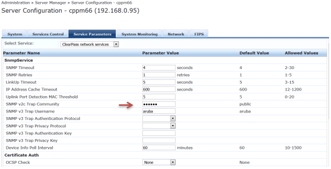
Here we need to configure SNMP Traps that will be coming in from Aruba 2920 switch.
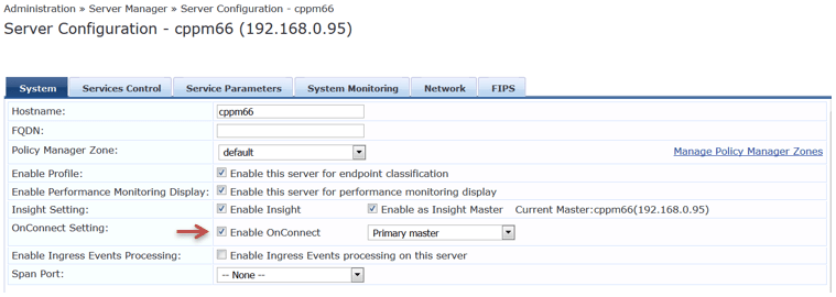
Next you need to enable OnConnect
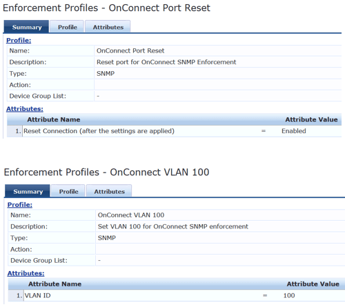
Then create your enforcement profiles that we’ll use in our policy.
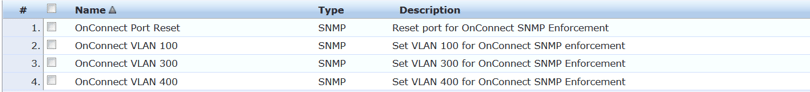
Here are the details of the profiles.

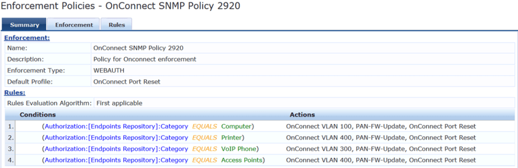
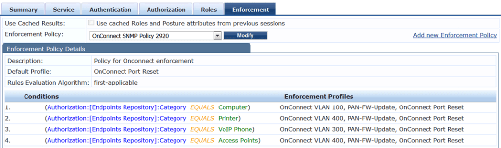
Here is the enforcement policy that we’ll use.
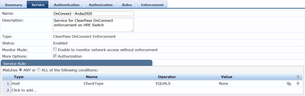
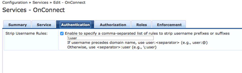
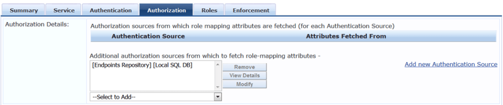
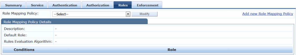
Creating Your Services
You can create your OnConnect service using the template from here.
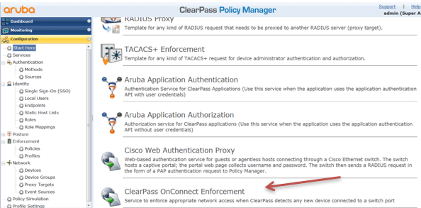
However I have used manual process to create my OnConnect service. Here is the summary view.
Aruba Switch Configuration
You need to ensure Aruba2920 or 2930F/M switches are running 16.01 or later software version.
Here is the SNMP configuration
HP-2920-24G-PoEP# conf t
snmp-server community "public" unrestricted
snmp-server community "Passw0rd" operator unrestricted
snmp-server community "private-write" unrestricted
snmp-server community "public-read" operator
snmp-server host 192.168.0.95 community "public" trap-level all
snmp-server enable traps mac-notify trap-interval 1
snmp-server enable traps mac-notify

HP-2920-24G-PoEP#
and VLAN and routing configuration
vlan 1
   name "DEFAULT_VLAN"
   no untagged 1-16,21-22
   untagged 17-20,23-24
   no ip address
   exit
vlan 100
   name "IoT-Laptops"
   ip address 10.0.10.1 255.255.255.0
   ip helper-address 192.168.0.254
   ip helper-address 192.168.0.95
   exit
vlan 192
   name "VLAN192"
   untagged 1-4
   ip address 192.168.0.251 255.255.255.0
   exit
vlan 200
   name "Guest"
   untagged 15-16
   ip address 10.0.20.1 255.255.255.0
   ip helper-address 192.168.0.95
   ip helper-address 192.168.0.254
   exit
vlan 300
   name "IoT-webcams"
   ip address 10.0.30.1 255.255.255.0
   ip helper-address 192.168.0.95
   ip helper-address 192.168.0.254
   exit
vlan 400
   name "IoT-aps"
   ip address 10.0.40.1 255.255.255.0
   ip helper-address 192.168.0.254
   ip helper-address 192.168.0.95
   exit

ip route 0.0.0.0 0.0.0.0 192.168.0.1
ip routing

HP-2920-24G-PoEP#
Testing
So initially we ensure that the VLAN200 is assigned to ports 15-16.
vlan 200
   name "Guest"
   untagged 15-16
   ip address 10.0.20.1 255.255.255.0
   ip helper-address 192.168.0.95
   ip helper-address 192.168.0.254
   exit

HP-2920-24G-PoEP# sh interfaces status
  Port     Name       Status  Config-mode   Speed    Type       Tagged Untagged
  -------- ---------- ------- ------------- -------- ---------- ------ --------
  1                   Up      Auto          100FDx   100/1000T  No     192
  2                   Up      Auto          1000FDx  100/1000T  No     192
  3                   Down    Auto          1000FDx  100/1000T  No     192
  4                   Down    Auto          1000FDx  100/1000T  No     192
  5                   Down    Auto          1000FDx  100/1000T  30     10
  6                   Down    Auto          1000FDx  100/1000T  30     10
  7                   Down    Auto          1000FDx  100/1000T  30     10
  8                   Down    Auto          1000FDx  100/1000T  30     10
  9                   Down    Auto          1000FDx  100/1000T  30     10
  10                  Down    Auto          1000FDx  100/1000T  30     10
  11                  Down    Auto          1000FDx  100/1000T  30     10
  12                  Down    Auto          1000FDx  100/1000T  30     10
  13                  Down    Auto          1000FDx  100/1000T  No     30
  14                  Down    Auto          1000FDx  100/1000T  No     30
  15                  Down    Auto          1000FDx  100/1000T  No     200
  16                  Down    Auto          1000FDx  100/1000T  No     200
  17                  Down    Auto          1000FDx  100/1000T  No     1
  18                  Down    Auto          1000FDx  100/1000T  No     1
  19                  Down    Auto          1000FDx  100/1000T  No     1
  20                  Down    Auto          1000FDx  100/1000T  No     1
  21                  Down    Auto          1000FDx  100/1000T  No     10
  22                  Down    Auto          1000FDx  100/1000T  No     10
  23                  Down    Auto          1000FDx  100/1000T  multi  1
  24                  Down    Auto          1000FDx  100/1000T  multi  1

HP-2920-24G-PoEP#
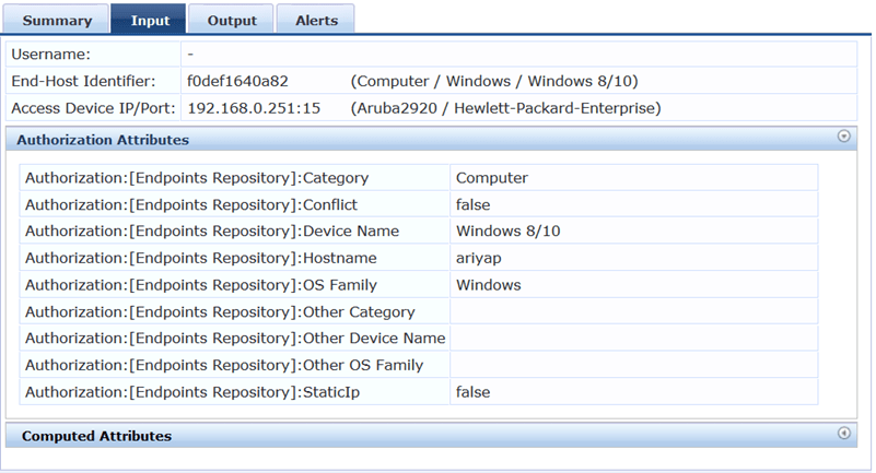
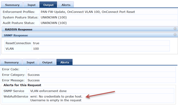
Now we are connecting the non-domain laptop to port 15.
First the laptop gets an IP in VLAN 200 (Guest). Then the switch send a SNMP trap to ClearPass. And based on the profiling category ClearPass sends back a SNMP config change and a port bounce.

In case you need to differentiate the domain laptops from others, you need to setup WMI profile. It’s under Configuration » Profile Settings. (I won’t cover it here.)
Here is the output of the interfaces on the switch, as you can see port 15 is now on VLAN 100
HP-2920-24G-PoEP# sh int st
  Port     Name       Status  Config-mode   Speed    Type       Tagged Untagged
  -------- ---------- ------- ------------- -------- ---------- ------ --------
  1                   Up      Auto          100FDx   100/1000T  No     192
  2                   Up      Auto          1000FDx  100/1000T  multi  192
  3                   Down    Auto          1000FDx  100/1000T  No     192
  4                   Down    Auto          1000FDx  100/1000T  No     192
  5                   Down    Auto          1000FDx  100/1000T  30     10
  6                   Down    Auto          1000FDx  100/1000T  30     10
  7                   Down    Auto          1000FDx  100/1000T  30     10
  8                   Down    Auto          1000FDx  100/1000T  30     10
  9                   Down    Auto          1000FDx  100/1000T  30     10
  10                  Down    Auto          1000FDx  100/1000T  30     10
  11                  Down    Auto          1000FDx  100/1000T  30     10
  12                  Down    Auto          1000FDx  100/1000T  30     10
  13                  Down    Auto          1000FDx  100/1000T  No     30
  14                  Down    Auto          1000FDx  100/1000T  No     30
  15                  Up      Auto          1000FDx  100/1000T  No     100
  16                  Down    Auto          1000FDx  100/1000T  No     200
  17                  Down    Auto          1000FDx  100/1000T  No     1
  18                  Down    Auto          1000FDx  100/1000T  No     1
  19                  Down    Auto          1000FDx  100/1000T  No     100
  20                  Down    Auto          1000FDx  100/1000T  No     1
  21                  Down    Auto          1000FDx  100/1000T  No     10
  22                  Down    Auto          1000FDx  100/1000T  No     10
  23                  Down    Auto          1000FDx  100/1000T  multi  1
  24                  Down    Auto          1000FDx  100/1000T  multi  1

HP-2920-24G-PoEP#
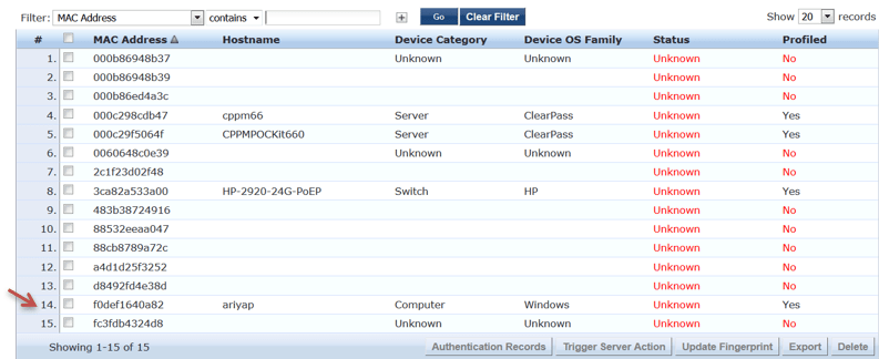
And when you check the Endpoint database, you should see the entry as profiled.

Leave a comment